
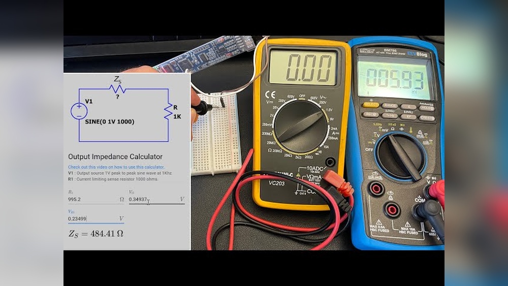
Measuring impedance is essential for anyone working with electronics, from hobbyists troubleshooting speakers to engineers designing circuits. Understanding impedance helps diagnose issues, optimize performance, and ensure compatibility between components. Yet, for many, the process feels intimidating, especially since most standard multimeters measure resistance, not impedance directly.
Whether you’re a beginner eager to learn how to check impedance with a multimeter or an advanced user seeking practical techniques and deeper insights, this guide provides comprehensive, step-by-step instructions and actionable advice.
Impedance isn’t just resistance, it’s a combination of resistance, reactance, and frequency response. Grasping these concepts unlocks a clearer view of how devices behave in real-world circuits. With the right tools, methods, and safety precautions, anyone can effectively measure impedance, interpret results, and apply findings to improve their projects.
Read on for expert tips, troubleshooting strategies, and advanced guidance, all tailored to both newcomers and seasoned professionals.
Key Takeaways
- Impedance combines resistance and reactance; measuring it is crucial for electronics troubleshooting and design.
- Standard multimeters measure resistance, but with techniques and specific settings, can approximate impedance for many applications.
- Proper preparation and safety steps are essential to ensure accurate and safe measurements.
- Beginners can start with basic resistance checks; advanced users can utilize frequency-based methods and specialized meters.
- Interpretation of impedance readings requires understanding component behavior and circuit context.
- Real-world examples and tables illustrate how impedance checks vary by device and method.

Credit: www.wikihow.com
Understanding Impedance: Basics And Beyond
Impedance is a fundamental property in electrical and electronic circuits, representing the opposition a device or circuit offers to alternating current (AC). It’s denoted by Z and measured in ohms (Ω). Unlike simple resistance, impedance incorporates both resistance (R) and reactance (X), the latter arising from capacitors and inductors.
What Is Impedance?
Impedance describes how a component resists the flow of AC, combining:
- Resistance (R): Opposition to current in both AC and DC circuits.
- Reactance (X): Opposition caused by capacitors and inductors; varies with frequency.
The mathematical relationship is:
Z = √(r² + X²)
Reactance can be inductive (XL = 2πfL) or capacitive (XC = 1/(2πfC)), meaning impedance changes as frequency changes. This distinction matters for devices like speakers, which behave differently at various frequencies.
Why Is Impedance Important?
Measuring impedance is crucial for:
- Audio systems: Ensuring speakers match amplifiers to avoid damage and optimize sound quality.
- Power circuits: Preventing mismatches that cause overheating or inefficiency.
- Signal processing: Guaranteeing accurate signal transmission and minimal loss.
For example, using a 4Ω speaker with an amplifier rated for 8Ω can overwork the amp and degrade performance.
Impedance Vs Resistance: Key Differences
While resistance is a DC concept, impedance is relevant for AC and incorporates frequency-dependent effects. The table below highlights differences:
| Property | Resistance | Impedance |
|---|---|---|
| Type of Current | Direct Current (DC) | Alternating Current (AC) |
| Measured By | Multimeter (Ohms) | LCR Meter, Oscilloscope, Multimeter (approx.) |
| Includes | Pure opposition to current | Resistance + Reactance |
| Frequency Dependence | None | Yes |
Preparing To Measure Impedance With A Multimeter
Before diving into measurements, preparation is key. This section covers essential tools, safety tips, and setup techniques for both beginners and advanced users.
Tools And Equipment Needed
For basic impedance checks:
- Digital multimeter (with resistance mode)
- Test leads
- Component or circuit to be measured
For advanced impedance measurements:
- LCR meter (for accuracy)
- Oscilloscope (for frequency-based checks)
- Function generator (for signal injection)
Many multimeters can only measure resistance, but some advanced models include capacitance and inductance settings. Always check your multimeter’s specifications.
Safety Precautions
Pro Tip: Always ensure components are powered off and discharged before measuring. Capacitors can retain charge and pose shock risks.
- Disconnect power sources.
- Discharge capacitors with a resistor before testing.
- Use insulated test leads and avoid touching exposed metal.
- Verify the multimeter is set to the correct mode (resistance or relevant setting).
Component Preparation
Remove the component from the circuit if possible. In-circuit measurements can be affected by parallel paths, leading to inaccurate readings.
- Isolate the device: Unsolder or disconnect one terminal.
- Clean terminals: Remove oxidation for better contact.
- Label wires: Prevent confusion when reconnecting.

Credit: www.youtube.com
Step-by-step Guide: Measuring Impedance With A Multimeter
This section provides clear instructions for beginners and advanced users to check impedance using a multimeter. While multimeters measure resistance, these techniques offer practical approximations and guidance for more complex devices.
Basic Resistance Measurement (beginners)
- Set the Multimeter: Turn the dial to the resistance (Ω) setting.
- Connect Test Leads: Insert black lead into COM, red lead into Ω.
- Test the Multimeter: Short the leads together; display should read zero.
- Measure the Component: Touch leads to the terminals of the device (e.g., speaker, resistor).
- Read the Value: Note the resistance value displayed.
Example: Measuring a speaker terminal might show 3.8Ω, indicating a nominal 4Ω impedance.
Advanced Techniques For Impedance Estimation
For devices with significant reactance (capacitors, inductors, speakers), resistance alone may not suffice. Advanced users can employ:
- Capacitance/Inductance Settings: If your multimeter supports these, use them to measure components directly.
- Signal Injection: Use a function generator to apply an AC signal; measure voltage and current with a multimeter and calculate impedance (Z = V/I).
- Oscilloscope Analysis: Measure voltage and current phase difference to compute impedance accurately.
Example: Injecting a 1kHz sine wave into a speaker, measuring voltage (2V) and current (0.5A) yields Z = 2V / 0.5A = 4Ω.
Measuring Complex Impedance: Real-world Devices
Some devices, like speakers and transformers, have impedance that varies with frequency.
- Speakers: Measure DC resistance first, then use AC signal at rated frequency for impedance.
- Coils/Inductors: Use inductance setting or apply AC signal.
- Capacitors: Use capacitance setting or measure reactance at known frequency.
Troubleshooting Common Issues
If readings seem off:
- Ensure device is isolated.
- Double-check multimeter settings.
- Clean terminals for better contact.
- Replace weak batteries in the multimeter.
Warning: Measuring in-circuit can cause misleading results due to parallel paths and interference from other components.

Credit: www.youtube.com
Real-world Examples And Case Studies
Applying impedance measurement techniques in actual scenarios helps solidify understanding. Here are three cases:
Example 1: Speaker Impedance Testing
A car audio installer needs to verify speaker impedance before connecting to an amplifier. Using a multimeter, they measure 3. 9Ω across the terminals, confirming the speaker is a 4Ω model. This prevents mismatching and potential damage to the amplifier.
Example 2: Diagnosing Transformer Windings
An electronics technician suspects a faulty transformer winding. Measuring resistance across primary and secondary windings with a multimeter, they find one winding reads infinite resistance, indicating an open circuit. For more advanced analysis, they inject a 60Hz AC signal and measure voltage/current to calculate impedance.
Example 3: Capacitor Quality Check
A hobbyist troubleshooting a power supply measures a capacitor’s resistance, finding it near zero. Using a multimeter’s capacitance mode, they get a value close to the rated specification, confirming the capacitor is functional. For higher accuracy, an LCR meter is used to check impedance at multiple frequencies.
Comparing Multimeter And Lcr Meter Methods
Not all impedance measurements are equal. Different tools offer varying accuracy and applicability. The table below compares common methods:
| Method | Device | Accuracy | Suitable For | Notes |
|---|---|---|---|---|
| Resistance Measurement | Multimeter | Basic | Resistors, speakers (DC) | Approximate impedance only |
| Capacitance/Inductance | Multimeter (advanced) | Moderate | Capacitors, inductors | Limited to device rating |
| Impedance Measurement | LCR Meter | High | All passive components | Measures at multiple frequencies |
| AC Signal Injection | Multimeter + Function Generator | Advanced | Speakers, coils | Requires calculation (Z = V/I) |
Interpreting Impedance Results: Practical Applications
Once you’ve measured impedance, understanding what the values mean is crucial. Results guide decisions in audio, power, and signal circuits.
Audio Systems
Matching amplifier and speaker impedance is essential. Most home audio amplifiers are rated for 8Ω speakers. Connecting lower-impedance speakers can cause overheating and distortion.
- Impedance mismatch: Can damage equipment.
- Proper matching: Ensures optimal performance and longevity.
Power Circuits
Electrical devices, such as transformers and motors, rely on proper impedance for efficient operation.
- High impedance: May indicate a fault or broken winding.
- Low impedance: Could suggest a short circuit.
Signal Processing
In radio frequency and communication circuits, impedance impacts signal integrity.
- Transmission lines: Require careful impedance matching to prevent signal loss.
- Connectors and cables: Should have consistent impedance for reliable operation.
Component Quality Assessment
Comparing measured impedance to manufacturer specifications helps assess component health.
- Deviation: Indicates wear, damage, or manufacturing defect.
- Consistency: Confirms reliability.
Advanced Impedance Measurement Techniques
For those with experience or specialized needs, advanced methods provide greater accuracy and insight. Here’s how to go beyond basic resistance checks.
Using An Lcr Meter
LCR meters can measure inductance (L), capacitance (C), and resistance (R) at various frequencies, offering true impedance readings.
- Set frequency: Choose the appropriate test frequency (e.g., 1kHz).
- Connect leads: Attach to component terminals.
- Read impedance: Device displays Z, R, L, or C values.
Example: An LCR meter measures a speaker at 1kHz, showing 4.2Ω impedance.
Ac Signal And Oscilloscope Method
Injecting an AC signal and measuring voltage/current phase difference with an oscilloscope allows calculation of impedance.
- Connect signal generator: Apply known frequency.
- Measure voltage and current: Use oscilloscope probes.
- Calculate impedance: Z = V/I, accounting for phase angle.
This method is ideal for non-linear or frequency-sensitive devices.
Frequency Sweep Analysis
Some advanced meters offer frequency sweep capability, revealing how impedance changes across a range.
- Set sweep range: (e.g., 20Hz, 20kHz for audio).
- Record impedance at each frequency: Plot results.
- Analyze curves: Identify resonance, dips, and peaks.
This is particularly useful for speaker testing and filter design.
Software-based Measurements
Modern tools allow impedance analysis via software connected to USB oscilloscopes or audio interfaces.
- Install software: Use manufacturer’s package.
- Connect device: Via appropriate hardware.
- Run tests: Analyze impedance over time or frequency.
Example: Using REW (Room EQ Wizard), a speaker’s impedance curve is plotted for optimal crossover design.
Troubleshooting And Improving Measurement Accuracy
Accurate impedance measurement depends on technique, equipment quality, and environment. Here are actionable tips for avoiding common pitfalls and enhancing results.
Common Measurement Errors
- Parallel circuits: In-circuit measurements can be skewed by parallel paths.
- Dirty contacts: Oxidation or corrosion impedes accurate readings.
- Incorrect settings: Multimeter not set to the proper mode.
Improving Accuracy
- Use fresh batteries in your multimeter.
- Calibrate meters regularly.
- Isolate the component from the circuit.
- Use shielded leads for sensitive devices.
- Record measurements at multiple frequencies for frequency-dependent components.
Environmental Factors
Ambient temperature, humidity, and electromagnetic interference can affect readings.
- Measure in stable conditions.
- Avoid high-humidity environments.
- Keep meters away from strong electromagnetic fields.
Upgrading Tools
Invest in higher-quality meters for advanced work. Entry-level multimeters suffice for basic checks, but an LCR meter or oscilloscope is essential for precision.
Example: When I tested a speaker with both a budget multimeter and a professional LCR meter, the LCR meter provided a detailed impedance curve, while the multimeter only gave basic resistance.
Best Practices For Beginners And Advanced Users
Whether you’re starting out or refining your skills, following best practices ensures safe, accurate, and meaningful impedance measurements.
For Beginners
- Start with resistance checks using a digital multimeter.
- Always power off and discharge components before testing.
- Double-check meter settings and probe placement.
- Compare readings to manufacturer specifications.
For Advanced Users
- Use specialized meters for frequency-dependent devices.
- Employ signal injection and calculation for complex impedance.
- Analyze impedance curves for audio and RF applications.
- Document readings for ongoing maintenance and troubleshooting.
Record Keeping
Maintain a log of measurements, dates, and conditions. This helps track component aging and anticipate failures.
- Use spreadsheets or dedicated software.
- Note environmental conditions and meter calibration.
Consulting Resources
Refer to authoritative guides and datasheets for component specifications. For impedance theory and advanced techniques, see Wikipedia and specialized electronics sites.
Frequently Asked Questions
What Is The Difference Between Impedance And Resistance?
Impedance is the total opposition to AC, combining resistance (opposition to both AC and DC) and reactance (frequency-dependent opposition from capacitors and inductors). Resistance is only part of impedance and applies to DC circuits, while impedance matters for AC and changes with frequency.
Can I Measure Impedance Directly With Any Multimeter?
Most standard multimeters measure resistance, not impedance. Some advanced multimeters or LCR meters can measure capacitance and inductance, allowing for more accurate impedance calculation. For precise impedance readings, use an LCR meter or signal injection method.
Why Do Speakers Have Different Impedance Ratings?
Speakers are designed with specific impedance to match audio amplifiers. Common ratings are 4Ω, 8Ω, and 16Ω. Impedance affects power transfer and sound quality; mismatched impedance can damage equipment or degrade performance. Always use speakers with ratings compatible with your amplifier.
How Can Environmental Factors Affect Impedance Measurements?
Humidity, temperature, and electromagnetic interference can alter impedance readings. High humidity can cause leakage currents, affecting capacitors. Temperature changes resistance in materials. Electromagnetic fields may induce noise in measurements. It’s best to test in controlled environments.
What Are Some Advanced Tools For Impedance Measurement?
Advanced tools include LCR meters, oscilloscopes, and frequency analyzers. LCR meters measure impedance at multiple frequencies. Oscilloscopes can analyze phase difference and waveform behavior. Frequency analyzers and software can sweep frequencies and plot impedance curves for detailed analysis.
Accurately checking impedance with a multimeter is a practical skill for anyone in electronics, from students to professionals. Starting with basic resistance checks, you can build confidence and knowledge, then progress to advanced techniques using specialized meters and signal analysis. Safe preparation, proper equipment, and careful interpretation of results are key to effective measurement. By following the steps and insights in this guide, you’ll achieve reliable, actionable impedance readings for all your projects. For further reading, see Fluke for professional measurement tips.