

Using an analog multimeter is an essential skill for anyone interested in electronics, automotive work, or electrical maintenance. Unlike digital meters, analog models display readings using a needle and scale, which can reveal fluctuations and trends in real time, making them invaluable for diagnosing intermittent faults.
For beginners, the classic analog design may seem intimidating, but with the right approach, it provides a hands-on understanding of electrical measurements. At the same time, advanced users can leverage the analog multimeter’s sensitivity and real-time feedback for nuanced troubleshooting.
This guide delivers a step-by-step tutorial on how to use an analog multimeter, suitable for both beginners and advanced users. You’ll learn about the device’s components, safe operation, and real-world application, with practical examples, comparison tables, and actionable tips. Whether you’re checking household batteries, diagnosing a faulty appliance, or teaching the next generation of engineers, mastering this tool is a fundamental building block in your technical toolkit.
Key Takeaways
- Analog multimeters offer real-time feedback, making them ideal for detecting voltage fluctuations and trends.
- Beginners should focus on understanding the meter’s range settings, probe handling, and safety precautions.
- Advanced users can exploit the meter’s sensitivity for troubleshooting complex electronic and automotive systems.
- Proper calibration, maintenance, and interpretation of scales are critical for accurate readings.
- Real-world examples and comparison tables help clarify common tasks and differences between analog and digital meters.

Credit: www.youtube.com
Understanding The Analog Multimeter
The analog multimeter, often called a VOM (Volt-Ohm-Milliammeter), measures voltage, current, and resistance using a moving-coil meter and pointer. Unlike digital meters that provide direct numerical readings, analog models require you to interpret needle position on a calibrated scale. This section explores the components, functionality, and types of analog multimeters.
Main Components
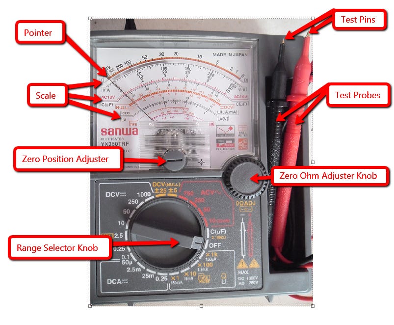
Analog multimeters consist of several key parts:
- Moving-coil meter: The heart of the device, displaying readings via a needle.
- Selection knob (range selector): Chooses measurement type (voltage, current, resistance) and range.
- Test probes: Usually black (common/negative) and red (positive), used to contact the circuit.
- Terminals: Input jacks for probes, typically marked as COM (common), VΩmA, and sometimes a high-current port.
- Scale display: Multiple graduated scales for different measurements.
- Zero adjust knob: For calibrating the needle to zero, especially important for resistance measurements.
- Mirror strip: Helps reduce parallax error by aligning the needle’s reflection with the scale.
How An Analog Multimeter Works
An analog multimeter works by converting electrical energy from the measured circuit into a magnetic field within the moving-coil meter. The interaction of this field with a permanent magnet deflects the needle proportionally to the measured value.
- Voltage (V): Measured by connecting the multimeter in parallel with the circuit.
- Current (A): Measured by connecting in series; current flow causes needle deflection.
- Resistance (Ω): An internal battery sends a small current through the component, and the meter measures the resulting deflection.
Pro Tip: The analog meter’s needle moves smoothly, allowing you to observe fluctuations that a digital meter may miss.
Types Of Analog Multimeters
There are two main types:
- Standard analog multimeters: Basic models for general electrical tasks.
- High-sensitivity analog multimeters: Feature higher impedance (e.g., 20kΩ/V or more), minimizing their impact on sensitive circuits.
A few models offer extra functions, like transistor testing or capacitance measurement, but they are less common.
Comparison: Analog Vs. Digital Multimeters
Understanding the differences between analog and digital multimeters is key for choosing the right tool. The following table summarizes the main distinctions:
| Feature | Analog Multimeter | Digital Multimeter (DMM) |
|---|---|---|
| Display | Needle and scale | Numeric LCD/LED |
| Response to Fluctuations | Real-time, smooth | May “jump” or lag |
| Sensitivity to Small Changes | High | Moderate |
| Reading Accuracy | User-dependent (parallax error) | Consistent, easy to read |
| Durability | More robust to electrical overload | Can be damaged by high voltage/current |
| Best Use Cases | Trend analysis, training | Precise measurement, data logging |
Getting Started: Preparation And Safety
Before measuring, it’s crucial to prepare your analog multimeter and workspace to ensure safety and accuracy. This section is particularly vital for beginners but includes advanced precautions for seasoned technicians.
Inspecting Your Multimeter
Begin by visually examining your multimeter:
- Check the probes: Ensure insulation is intact and there are no exposed wires.
- Inspect the meter body: Look for cracks, loose knobs, or damaged terminals.
- Test the meter: Move the needle with the zero adjust knob. It should respond smoothly without sticking.
If you find any damage, replace the affected part before proceeding.
Understanding Measurement Ranges
Every multimeter has several ranges for voltage, current, and resistance. Selecting the correct range is critical:
- Start with the highest range: This prevents needle “peg” (over-deflection), which can damage the meter.
- Fine-tune for accuracy: Once you see the reading is low, switch to a lower range for better precision.
Example: If you expect to measure a 12V battery, start on the 50V range, then step down to 10V or 15V if available.
Safety Precautions
Both beginners and advanced users must respect electrical safety:
- Always start with the meter OFF and probes disconnected.
- Never measure resistance on a live circuit. Remove power before testing continuity or resistance.
- Be cautious with high voltages. Use one hand, keep the other away, and stand on an insulating mat if possible.
- Observe polarity: For DC voltage/current, connect the black probe to the negative (ground) and red to the positive terminal.
Warning: Never exceed the meter’s maximum voltage or current rating. Doing so can damage the meter and pose a shock hazard.
Calibration And Zeroing
Proper calibration ensures accurate readings, especially for resistance:
- Short the probes together on the Ω range.
- Use the zero adjust knob to set the needle to the “0 Ω” mark.
- Repeat every time you change the resistance range.
Advanced users may also calibrate their meter using reference resistors or calibration sources.

Credit: www.wikihow.com
Step-by-step: Measuring Voltage, Current, And Resistance
This section provides detailed, beginner-friendly instructions for measuring voltage, current, and resistance, with tips for advanced accuracy.
Measuring Voltage (ac And Dc)
Step 1: Set The Meter
- Turn the selection knob to the appropriate voltage type: DCV for batteries/circuits, ACV for mains or transformers.
- Choose the highest range above your expected value.
Step 2: Connect The Probes
- Insert the black probe into the COM terminal, red into the VΩmA terminal.
- For DC, connect black to circuit ground/negative, red to positive.
Step 3: Take The Measurement
- Observe the needle’s position on the correct voltage scale.
- If the needle barely moves, select a lower range for precision.
- If the needle pegs (hits the end), immediately switch to a higher range to avoid damage.
Step 4: Interpret The Scale
- Analog meters typically have multiple scales (e.g., 0-10, 0-50, 0-250).
- Read the scale that matches your selected range.
- If the needle points to “6” on a 0-10V scale, the voltage is 6V.
Pro Tip: For rapidly fluctuating signals, watch the needle’s average position for a good estimate.
Measuring Current (amperes)
Step 1: Set The Meter
- Turn the knob to the appropriate current range (DCA for DC, ACA for AC).
- Start with the highest range.
Step 2: Break The Circuit
- To measure current, you must open the circuit and connect the meter in series.
Step 3: Insert The Meter
- Black probe to COM, red probe to the current input (may be labeled as mA or 10A for higher ranges).
- Complete the circuit through the meter.
Step 4: Read And Interpret
- Note the needle’s position on the matching current scale.
- Adjust to a lower range if the reading is too small.
Warning: Never attempt to measure current by placing the meter across a voltage source. This can short-circuit the source and damage the meter.
Measuring Resistance (ohms)
Step 1: Set The Meter
- Select the Ω (ohms) range.
- For unknown resistances, start at the highest range.
Step 2: Zero The Meter
- Short the probes together and adjust the zero knob until the needle points to “0 Ω”.
Step 3: Connect To Component
- Ensure the component is disconnected from all power.
- Place one probe on each end of the resistor or wire.
Step 4: Interpret The Scale
- Read the resistance value where the needle points.
- Multiply by the range factor (e.g., “×1”, “×10”, “×1k”).
Example: If the needle points to “5” on the ×10 scale, resistance is 50 Ω.
Pro Tip: If measuring in-circuit, remove at least one end of the resistor to avoid parallel paths affecting the reading.
Table: Typical Measurement Scenarios
The following table summarizes common tasks and recommended ranges:
| Task | Expected Value | Recommended Range | Connection Type |
|---|---|---|---|
| Check AA battery voltage | 1.5V DC | 0-10V DC | Parallel |
| Household mains voltage | 110, 240V AC | 0-250V AC | Parallel |
| LED forward current | 10, 30mA DC | 0-50mA DC | Series |
| Resistor value | 100Ω, 10kΩ | ×10 or ×1k Ω | Across resistor |
Credit: medium.com
Advanced Techniques And Real-world Examples
Beyond basic measurements, analog multimeters provide powerful diagnostic tools for advanced users and real-world troubleshooting. This section offers case studies, advanced suggestions, and in-depth techniques.
Detecting Intermittent Faults
Example: An appliance occasionally cuts out, but works when tapped.
- Connect the meter across the suspect connection (e.g., switch contacts).
- Observe the needle while gently tapping or flexing wires.
- Fluctuations on the analog meter reveal poor connections or intermittent shorts, something digital meters may not display.
Testing Capacitors (qualitative)
While not precise, analog multimeters can indicate capacitor health:
- Set the meter to a medium resistance range.
- Discharge the capacitor fully.
- Connect probes: The needle should swing right (low resistance) then slowly fall left (charging), indicating the capacitor is taking a charge.
- No needle movement or immediate “0 Ω” suggests a shorted or open capacitor.
Pro Tip: For more accurate capacitance measurement, use a dedicated meter. The analog multimeter provides only a basic go/no-go test.
Diode And Continuity Testing
- Set the meter to the lowest resistance range.
- Place probes across the diode (observe polarity).
- A healthy diode shows low resistance in one direction and high in the other.
- For continuity, a near “0 Ω” reading indicates a closed circuit.
Automotive Applications
Case Study: Diagnosing a car’s charging system.
- Measure battery voltage with the engine off (should be ~12.6V for a healthy battery).
- Start the engine; measure again (should rise to 13.8, 14.5V if the alternator is charging).
- Observe the analog needle for fluctuations, which may indicate a faulty voltage regulator.
Troubleshooting Tips For Advanced Users
- Use high-impedance meters when working with delicate electronic circuits to avoid loading effects.
- Check for “leakage current” in insulation by measuring resistance between conductors, values should be very high (megohms).
- Monitor voltage drop across fuses or connectors to identify high-resistance faults.
Example: When I tested a vintage amplifier, the analog meter’s needle revealed a subtle “twitch” every time I adjusted the volume, indicating a dirty potentiometer.
Calibration, Maintenance, And Care
Proper care and calibration extend your analog multimeter’s life and ensure ongoing accuracy.
Regular Calibration
- Use a known reference voltage or resistance (calibration standard).
- Adjust internal trimmers if available, following the service manual.
- Compare readings with a calibrated digital meter for cross-verification.
Battery And Fuse Replacement
- Most analog multimeters use a 1.5V or 9V internal battery for resistance measurements.
- Replace the battery when resistance readings become unreliable or the zero-adjust fails.
- Replace blown fuses with exact type and rating to maintain protection.
Pro Tip: Always turn off the meter and remove probes before servicing.
Cleaning And Storage
- Clean the meter case with a soft, dry cloth.
- Store in a dry, dust-free environment.
- Keep probes untangled and avoid storing under tension.
Dealing With Common Issues
- Sticking needle: Gently tap the case or check for debris inside.
- Flickering readings: Inspect probes and connections for wear.
- Scale fading: Keep the meter out of direct sunlight.
Interpreting Scales And Reducing Errors
Analog multimeters require careful reading of scales and awareness of potential errors.
Reading The Scale Correctly
- Identify the correct scale for your measurement and range.
- View the needle straight-on, aligning with the mirror strip to avoid parallax error.
- Multiply by the range factor (e.g., “×10”, “×100”) if indicated.
Minimizing Errors
- Avoid touching probe tips to prevent body resistance from affecting readings.
- Use the highest practical range for voltage/current to protect the meter.
- Zero the needle before every resistance measurement.
Table: Common Sources Of Error
| Error Source | Effect | Correction |
|---|---|---|
| Parallax error | Misreading scale | Use mirror strip for alignment |
| Wrong range selection | Over/under-range, needle peg | Start high, step down |
| Unzeroed resistance scale | Inaccurate resistance reading | Short probes, adjust zero |
| Contact resistance | False high readings | Clean probes, firm contact |
Advanced Suggestions: Measurement Confidence
For high-precision work:
- Repeat measurements and average results to reduce random error.
- Compare with a digital meter for verification.
- Document readings with date, range, and environmental conditions, especially in professional settings.
Teaching Analog Multimeter Skills
Educators and mentors play a vital role in passing on analog multimeter skills. The hands-on nature of analog meters makes them excellent teaching tools, fostering a deeper understanding of electricity.
Structured Learning Steps
- Introduce meter anatomy: Hands-on exploration of parts and functions.
- Demonstrate safe operation: Guided voltage and resistance measurements.
- Practice interpreting scales: Use simulated readings before live circuits.
- Assign troubleshooting tasks: Encourage students to diagnose simple faults.
Group Activities And Labs
- Battery check relay: Students rotate through checking different battery types, recording voltage and needle movement.
- Fault simulation: Set up circuits with hidden faults; students use meters to locate the issue.
Assessment And Feedback
- Checklist assessments: Track safe handling, range selection, and reading accuracy.
- Peer teaching: Advanced students mentor beginners, deepening mastery for both.
Pro Tip: Use analog meters in parallel with digital meters during training, compare readings and discuss discrepancies.
Teaching Advanced Users
- Introduce advanced diagnostics (e.g., transient fault detection, leakage testing).
- Discuss the limitations and appropriate use cases for analog meters.
For more teaching resources, the Wikipedia Multimeter page offers a comprehensive overview of multimeter types and history.
Frequently Asked Questions
How Do I Avoid Damaging My Analog Multimeter?
To protect your analog multimeter, always start with the highest range when measuring unknown voltages or currents. Never measure resistance on a live circuit, ensure all power is disconnected first. Regularly inspect probes and replace damaged components promptly. Always observe the meter’s maximum voltage and current ratings, and replace blown fuses with the correct type.
What Does “sensitivity” Mean In Analog Multimeters?
Sensitivity is typically expressed in ohms per volt (Ω/V) and indicates how much the meter loads the circuit being measured. Higher sensitivity (e.g., 20,000 Ω/V) means the meter draws less current, making it suitable for sensitive electronic circuits. Lower sensitivity can cause measurement errors due to circuit loading, especially in high-impedance circuits.
Why Is The Needle Not Moving When I Measure Resistance?
If the needle does not move on resistance measurement, check that the internal battery is functional and properly installed. Ensure the zero-adjust has been set with probes shorted together. Also, confirm the component under test is not open or of a value beyond the selected range.
Replace the meter’s battery if resistance readings are consistently unreliable.
Can I Use My Analog Multimeter To Test Transistors Or Capacitors?
Some advanced analog multimeters have dedicated settings for transistor or capacitor testing, but most offer only qualitative checks. For transistors, you can test basic junction behavior using diode check methods. For capacitors, a charging “kick” observed on the resistance scale can indicate basic function, but it does not quantify actual capacitance.
For precise measurements, use specialized testers.
How Do I Calibrate My Analog Multimeter At Home?
To calibrate, compare your multimeter’s readings with a reliable reference, such as a precision voltage or resistor or a calibrated digital multimeter. Adjust the internal calibration trimmer as described in the service manual. For critical applications, consider professional calibration services.
Always document any calibration adjustments for future reference.
Resources For Further Learning
To deepen your knowledge, consider these authoritative resources:
- Fluke: What is a Multimeter?
- Local community college electronics courses
- Manufacturer manuals for your specific multimeter model
Mastering the analog multimeter opens the door to a world of practical electronics and electrical diagnostics. With hands-on practice, attention to detail, and a solid grasp of both basic and advanced techniques, you’ll be prepared to tackle troubleshooting challenges at any level.
Whether you’re a beginner developing foundational skills or an advanced user refining your diagnostic toolkit, the analog multimeter remains a vital and rewarding instrument for any technician or hobbyist.