
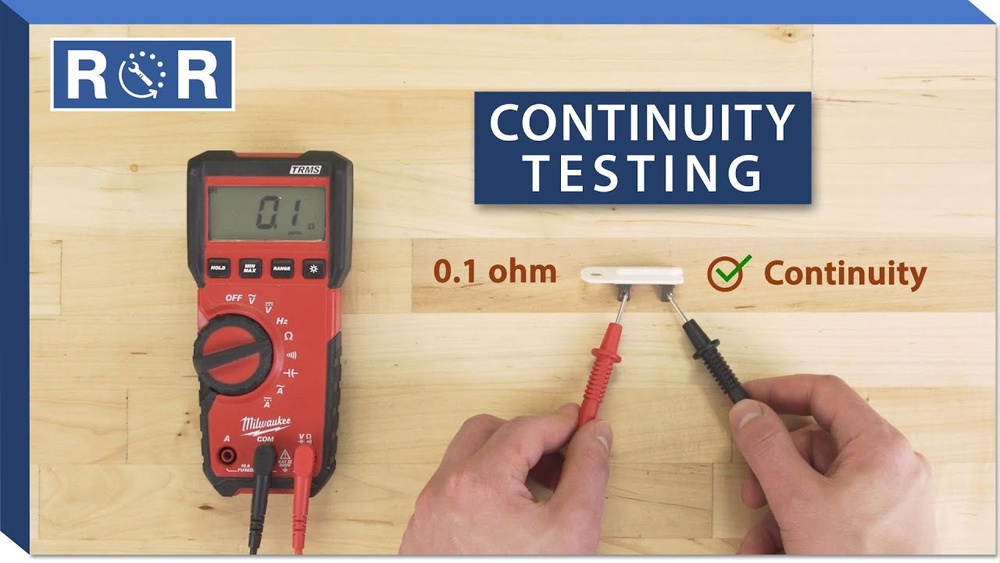
Testing earth continuity is a foundational practice in electrical safety, vital for everyone from home DIYers to professional electricians. Whether you’re installing a new outlet, troubleshooting a ground fault, or verifying compliance for industrial machinery, ensuring that the earth (ground) path is intact can prevent electric shocks, fires, and equipment damage.
But can you reliably test earth continuity with something as basic as a multimeter? Many beginners wonder if their everyday tool is up to the task or if specialized equipment is required.
This article will guide you step-by-step through testing earth continuity with a multimeter, highlighting both the simplicity and the limitations of this method. We’ll cover the principles behind earth continuity, explain the procedures for beginners, and provide advanced tips for pros.
You’ll see real-world examples, data-driven comparisons, and expert insights to ensure you’re using the right approach for your needs, and staying safe in the process.
Key Takeaways
- A digital multimeter can test earth continuity for basic verification, but it has limitations compared to dedicated earth testers.
- Correct test procedures and safety precautions are critical, mistakes can result in inaccurate readings or electrical hazards.
- Understanding resistance values is essential: A good earth path should have very low resistance, ideally less than 1 ohm for safety-critical systems.
- Professional, regulatory compliance often requires specialized testers and certified methods beyond a standard multimeter.
- Advanced users can supplement multimeter tests with additional checks, but should know when to escalate to more accurate equipment.

Credit: www.electricaltechnology.org
Understanding Earth Continuity And Its Importance
Earth continuity, also known as ground continuity, refers to the unbroken electrical connection between exposed conductive parts of an installation and the earth (ground). This path ensures that, if a fault occurs (such as a live wire touching a metal casing), the electrical current will safely flow to ground, tripping protective devices like circuit breakers.
Why Earth Continuity Matters
- Prevents electric shock: Faulty earth paths can turn metal appliances into shock hazards.
- Enables protective devices: Circuit breakers and fuses rely on a low-resistance earth path to disconnect power rapidly.
- Reduces fire risk: Proper grounding helps dissipate fault currents, minimizing overheating and potential fires.
- Meets safety codes: Electrical regulations (such as the NEC in the US or IEC internationally) mandate effective grounding.
Common Scenarios Requiring Earth Continuity Testing
- Installing or repairing outlets, switches, or lighting fixtures.
- Maintaining industrial machinery or server racks.
- Inspecting rental properties for compliance.
- Diagnosing tripping circuit breakers or unexplained shocks.
Basics Of Earth Continuity Circuits
An earth continuity path typically runs from the exposed metal parts through earth conductors (green or green/yellow wires) to a ground rod or earth plate. Any break or high resistance in this path compromises safety.
Pro Tip: Even experienced electricians sometimes overlook subtle sources of poor continuity, such as corroded terminal screws or loose bonding jumpers.

Credit: www.youtube.com
How Multimeters Work For Continuity Testing
A digital multimeter (DMM) is a versatile instrument used to measure voltage, current, and resistance. For continuity testing, it checks whether a path allows electrical current to flow, indicating a complete circuit.
Continuity Test Function Explained
Most DMMs feature a continuity mode, symbolized by a diode or sound wave. When enabled, the meter applies a small voltage across the probes and measures if the resistance is very low (typically below 30, 50 ohms), signaling continuity with a beep.
- Visual and audible feedback: The multimeter displays the resistance value and usually emits a beep for low-resistance paths.
- Not suitable for live circuits: Never use this mode on energized wires, it’s for de-energized testing only.
Resistance Measurement Vs. True Earth Testing
While a multimeter can show if a path is continuous and has low resistance, it does not inject the higher test currents that specialized earth continuity testers use. This means:
- Undetected high-resistance faults: Corroded or partially broken conductors might still show low resistance at a DMM’s low test current.
- No earth electrode testing: Multimeters cannot measure resistance to earth ground rods, only the continuity of conductors.
Multimeter Types: Analog Vs. Digital
Both analog and digital multimeters can test continuity, but digital models are more accurate and easier for beginners. They often include features like auto-ranging and clear beepers.
| Feature | Analog Multimeter | Digital Multimeter |
|---|---|---|
| Display | Needle scale | Digital (numeric) |
| Continuity Beeper | No | Yes (most models) |
| Accuracy | Moderate | High |
| Ease of Use | Intermediate | Beginner-friendly |
Example: Testing A Lamp’s Earth Wire
Suppose you’re repairing a desk lamp and want to ensure the green/yellow earth wire is continuous from the plug to the metal casing. Using the DMM’s continuity mode, you can place one probe on the earth pin of the plug and the other on the metal frame, if the meter beeps, the path is intact.

Credit: boilerfaultfinder.com
Step-by-step Guide: Testing Earth Continuity With A Multimeter
Testing earth continuity with a multimeter is straightforward but requires careful setup and attention to safety. This section provides a beginner-friendly walkthrough, followed by advanced tips for professionals.
Safety Precautions Before You Begin
- Always power off the circuit at the breaker or unplug the device.
- Verify zero voltage with the multimeter’s voltage function before touching wires.
- Wear insulated gloves and use insulated probes.
- Never test live circuits in continuity mode.
Required Tools And Preparation
- Digital multimeter (with continuity or resistance mode)
- Two test probes (red and black)
- Access to both ends of the earth conductor (e.g., earth pin on a plug and exposed metal part)
Step 1: Set The Multimeter To Continuity Or Resistance
- Turn the dial to the continuity symbol (sound wave/diode) if available; otherwise, select the lowest resistance (Ω) setting.
- Test the probes by touching them together, the meter should beep or display near-zero resistance.
Step 2: Connect The Probes To Each End Of The Earth Path
- Place one probe on the earth pin of a plug or the earth terminal in a distribution board.
- Place the other probe on the metal chassis or exposed conductive part you want to test.
Example: Testing the earth continuity in a wall outlet, one probe on the earth terminal inside the socket, the other on the earth bar in the consumer unit.
Step 3: Interpret The Results
- Beep or 0, 1 ohm reading: Good continuity.
- No beep or high resistance: Faulty or broken earth connection.
- Slight resistance (1, 2 ohms): May indicate a long cable run or minor connection resistance; investigate further if in doubt.
Warning: If you read infinite resistance (open circuit), do not use the equipment until the earth issue is fixed.
Step 4: Document Your Test
For installations, record:
- Tested points (e.g., outlet to earth bar)
- Measured resistance
- Date and initials
This is especially important in commercial and rental properties for compliance.
Advanced: Testing Bonding And Supplementary Earths
Advanced users may need to verify bonding conductors (which connect metal pipes, structural steel, etc.) or test supplementary earth paths.
- Use longer test leads or crocodile clips for distant points.
- For multi-point bonding, test between all pairs of exposed parts.
- Document any resistance above 1 ohm for investigation.
Limitations Of Using A Multimeter For Earth Continuity
While a multimeter is convenient, it has several inherent limitations when used for earth continuity testing, especially in professional or regulatory contexts.
Low Test Current Limits Accuracy
Multimeters use tiny test currents (usually less than 1 mA). This is safe, but it means:
- Loose or corroded connections may still pass the test.
- Parallel earth paths can mask breaks in one conductor.
Not Suitable For Earth Electrode Testing
A multimeter cannot measure the resistance from an earth rod or plate to the actual earth (soil). Proper earth resistance testing requires injecting a higher current and measuring voltage drop with a dedicated tester.
Compliance And Certification Issues
For installations that must meet IEC 60364, BS 7671, or NEC standards, only certified earth continuity testers or specific methods are acceptable. Multimeter results may not satisfy regulatory requirements.
False Positives And Negatives
- False positive: Parallel conductive paths (e.g., water pipes) may give a continuity reading even if the primary earth conductor is broken.
- False negative: Oxidized or dirty contact points can appear open when they are only resistive.
Professional Recommendations
The Institute of Electrical and Electronics Engineers (IEEE) and national standards recommend using dedicated testers for formal verification. See the Wikipedia article on earth ground resistance for a technical overview.
Pro Tip: Use a multimeter for quick checks or diagnostics, but switch to a dedicated tester for compliance, installations, or when in doubt.
Real-world Case Studies And Examples
Learning from practical examples is one of the best ways to understand earth continuity testing. Here are three scenarios, from basic to advanced.
Example 1: Homeowner Checks Outlet Grounding
A homeowner in an older house suspects grounding issues after receiving a mild shock from a metal lamp. Using a digital multimeter:
- Powers off the circuit at the breaker.
- Sets the DMM to continuity mode.
- Tests between the earth terminal in the outlet and the metal casing of the lamp.
Result: No beep. Investigation finds the earth wire disconnected at the outlet. After repair, the multimeter beeps, confirming restored continuity.
Example 2: Industrial Electrician Verifies Machine Bonding
An industrial electrician is tasked with verifying supplementary bonding in a large machine enclosure. Using a DMM:
- Tests continuity between the main earth bar and various metal panels.
- Finds one panel with 8 ohms resistance, well above the 1-ohm target.
- Locates and tightens a loose bonding jumper, reducing resistance to below 1 ohm.
This quick check ensures safety until a full test can be performed with a dedicated earth tester.
Example 3: Facilities Manager Audits Rental Units
A facilities manager audits a block of rental apartments before new tenants move in. Using a DMM, they:
- Record earth continuity readings for each outlet.
- Document higher-than-expected resistance in one apartment.
- Engage a qualified electrician, who discovers a partially severed earth conductor in the wall.
This process prevents future hazards and provides documentation for compliance.
Comparison: Multimeter Vs. Earth Continuity Tester
To clarify where a standard multimeter fits in, compare it side-by-side with a professional earth continuity tester.
| Feature | Digital Multimeter | Earth Continuity Tester |
|---|---|---|
| Test Current | <1 mA | 200 mA or higher |
| Suitable for Quick Checks | Yes | Yes |
| Regulatory Compliance | No | Yes |
| Accuracy for Low Resistance | Basic | High |
| Can Test Earth Rod Resistance | No | Yes (with proper method) |
| Price Range | $20, $100 | $200, $1000+ |
Advanced Earth Continuity Testing Techniques
If you’re an advanced user or professional, consider these techniques to go beyond the basics and address complex scenarios.
Testing Under Load
Sometimes, a conductor may pass a low-current continuity test but fail under real-world load (due to high resistance). To simulate real conditions:
- Use a load lamp (e.g., a 100W bulb) in series with the earth path.
- Observe if the lamp lights fully, indicating the path can carry significant current.
Four-wire (kelvin) Testing
For very low resistance paths, use a four-wire (Kelvin) measurement to eliminate the effect of lead resistance:
- Two wires supply current; two separate wires measure voltage drop.
- This is standard in laboratory and industrial earth bond testers.
Periodic And Automatic Testing
Modern facilities use automatic earth monitoring with built-in sensors that continuously check earth continuity and trigger alarms if it is lost.
Integration With Asset Management
Document all test results in a digital logbook or asset management system. This practice:
- Streamlines audits and inspections.
- Ensures traceability for insurance and regulatory purposes.
When To Upgrade Equipment
If you frequently test earth continuity or need compliance certification:
- Invest in a dedicated earth tester with logging, high test current, and earth electrode measurement.
- Some advanced multimeters include limited earth test functions, check specifications carefully.
Example: In my experience as an industrial engineer, using a high-current earth tester identified a hidden corrosion issue in a machine frame that a DMM failed to detect.
Troubleshooting Common Earth Continuity Problems
Even with good tools, you may encounter confusing results. Here’s how to troubleshoot the most common issues.
High Resistance Readings
- Check probe contact: Clean terminals and metal surfaces before testing.
- Inspect connections: Tighten terminal screws and check for corrosion.
- Test with a different multimeter: Rule out instrument faults.
No Continuity Detected
- Verify test points: Ensure you are testing the correct conductor ends.
- Check for parallel paths: Remove parallel bonding conductors during testing.
- Open circuit in wiring: Trace the conductor to find breaks.
Intermittent Or Fluctuating Readings
- Loose connections: Wiggle wires and observe meter response.
- Environmental factors: Moisture and temperature can affect readings, especially in outdoor installations.
Multiple Earth Paths
In complex systems, parallel paths (e.g., metal pipes) may mask faults. To isolate:
- Disconnect supplementary bonds during the test.
- Test each path individually.
Regulatory And Safety Considerations
Electrical regulations and best practices require more than a quick multimeter test for critical safety circuits.
Key Standards
- National Electrical Code (NEC) [US]: Mandates grounding and bonding for all premises wiring.
- IEC 60364 [International]: Details testing methods and safety thresholds.
- BS 7671 [UK Wiring Regulations]: Requires earth continuity verification with a minimum 200 mA test current.
When Is A Multimeter Test Sufficient?
- Basic household checks: Quick verification of outlets, appliances, or after minor repairs.
- Preliminary troubleshooting: Identifying obvious breaks before calling a professional.
When You Must Use A Certified Tester
- New installations: Before energizing, to comply with regulations.
- Periodic inspection: As required by law for rental, commercial, or industrial properties.
- Insurance and safety audits: Documentation must reference compliant test equipment.
Warning: For legal compliance and safety-critical environments, always consult a licensed electrician or qualified professional. For further reading, see the National Electrical Code (NEC) for US requirements.
Frequently Asked Questions
What Resistance Value Indicates A Good Earth Continuity?
A good earth continuity path should have a resistance well below 1 ohm. For general household circuits, anything under 1 ohm is typically acceptable, but for critical safety systems or as required by national standards, the maximum allowed may be 0.
5 ohms or even less. Always consult local electrical codes for the specific threshold.
Can I Test Earth Continuity While The Circuit Is Live?
No. Continuity tests with a multimeter must be performed only on de-energized circuits. Testing a live circuit risks damaging your meter, causing injury, or producing inaccurate results. If you need to verify grounding in an energized system, use a specialized device designed for live testing.
Why Does My Multimeter Show Continuity Even Though The Earth Wire Looks Broken?
This often happens when there are parallel grounding paths, for example, through metal pipes or other conductors bonded to ground. The multimeter detects continuity through these alternative paths, masking a break in the primary earth wire. Always isolate conductors before testing to ensure accurate results.
Is It Necessary To Test Earth Continuity After Every Repair Or Change?
Yes, it is best practice to test earth continuity after any repair, modification, or installation involving electrical wiring or devices. This ensures that you have not inadvertently broken or compromised the earth path, which could lead to safety hazards.
How Can I Improve The Accuracy Of My Earth Continuity Tests?
For better accuracy:
- Clean all contact points before testing.
- Use a dedicated earth continuity tester for critical applications.
- Employ four-wire (Kelvin) testing for very low-resistance paths.
- Minimize parallel paths during the test.
- Record and compare results periodically to identify degradation over time.
Performing thorough, accurate earth continuity tests not only protects property and lives but also ensures compliance and peace of mind.
Testing earth continuity with a multimeter is an accessible, beginner-friendly way to verify the integrity of ground paths in electrical systems. While a multimeter provides quick and valuable insights, its limitations mean it should be used for basic checks or troubleshooting, not for regulatory compliance or certification.
Advanced users and professionals should supplement multimeter tests with dedicated equipment and rigorous methods. By understanding both the capabilities and constraints of your testing tools, and by following best practices for safety and documentation, you can ensure reliable, safe electrical installations for homes and businesses alike.