
Digital multimeters and logic analyzers are two cornerstone tools for anyone working in electronics, engineering, or embedded systems. While both are indispensable for troubleshooting and development, they serve fundamentally different purposes, employ different measurement techniques, and cater to distinct user needs.
Understanding these differences is critical for choosing the right tool for your workflow, optimizing productivity, and avoiding costly mistakes.
If you’ve ever wondered why a professional engineer might reach for a logic analyzer instead of a digital multimeter, or vice versa, this article will clarify their roles from the ground up. We’ll bridge the gap from basic concepts to advanced use cases, providing guidance for beginners and seasoned pros alike.
Whether you’re a hobbyist, a student, or an experienced technician, you’ll find actionable insights, real-world examples, and expert tips to help you make informed decisions about when and how to use each instrument.
Key Takeaways
- Digital multimeters measure analog electrical parameters (voltage, current, resistance), while logic analyzers capture and analyze digital signals.
- Multimeters are best for circuit diagnostics and hardware troubleshooting; logic analyzers excel in digital protocol debugging and embedded system analysis.
- Choosing the right tool depends on your project’s signal type, required measurement speed, and data visualization needs.
- Logic analyzers typically support multi-channel high-speed data capture; multimeters provide single-point, real-time readings.
- Advanced users often combine both tools for comprehensive hardware and firmware debugging.
- Understanding core differences saves time, reduces errors, and improves design quality in electronics projects.
Understanding The Fundamentals
What Is A Digital Multimeter?
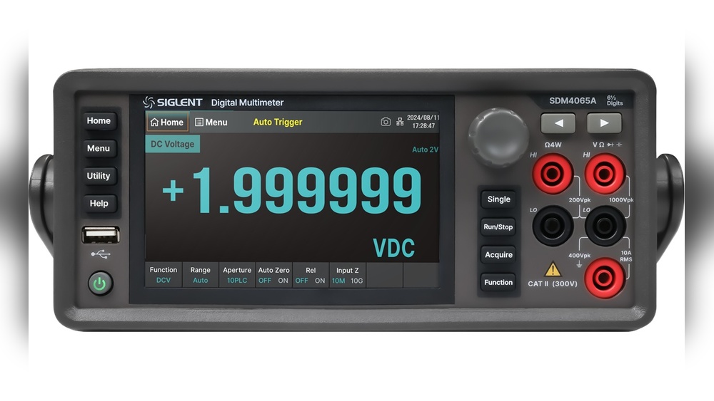
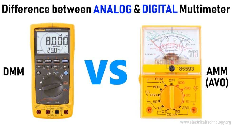
A digital multimeter (DMM) is an electronic measuring instrument that combines several measurement functions in one unit. At its core, a DMM measures:
- Voltage (AC/DC)
- Current (AC/DC)
- Resistance
Many advanced models also measure continuity, capacitance, frequency, temperature, and even diode/transistor characteristics. DMMs have become the default diagnostic tool for anyone working with electrical circuits, from household electricians to electronics engineers.
How A Digital Multimeter Works
A DMM uses analog-to-digital conversion to quantify electrical signals. When you connect the probes to a circuit, the device samples the signal, converts it to a digital value, and displays the result on an LCD. The design emphasizes accuracy, input protection, and ease of use.
Key Features
- Auto-ranging: Automatically selects the appropriate measurement range.
- Display: Digital readout, often with bar graphs for trends.
- Portability: Handheld or bench-top models.
- Safety: Fused inputs and overload protection.
What Is A Logic Analyzer?
A logic analyzer is a sophisticated instrument used for capturing and analyzing multiple digital signals simultaneously. Unlike a DMM, which measures continuous (analog) quantities, a logic analyzer is tailored for digital electronics, systems that process binary (0 or 1) signals.
How A Logic Analyzer Works
Logic analyzers connect to several points in a digital circuit (channels), sampling the logic level (high/low) of each channel at high speed. The captured data is then displayed as timing diagrams, protocol decodes, or state transitions, enabling users to debug timing issues, communication protocols, or embedded firmware.
Key Features
- Multi-channel input: Analyze 8, 16, or even hundreds of signals at once.
- High sampling rates: Capture events at speeds up to several GHz.
- Triggering: Start capture based on complex conditions.
- Protocol decoding: Interpret I2C, SPI, UART, CAN, and more.
Credit: www.electricaltechnology.org
Core Differences: Digital Multimeter Vs Logic Analyzer
To help visualize the distinctions, here’s a detailed comparison table:
| Feature | Digital Multimeter | Logic Analyzer |
|---|---|---|
| Measurement Type | Analog (Voltage, Current, Resistance) | Digital (Logic States, Timing, Protocols) |
| Signal Type | Continuous (Sine, DC, etc.) | Discrete (Binary 0/1) |
| Channels | Usually 1 (sometimes 2) | 8, 100+ simultaneous |
| Speed | Real-time, relatively slow updates | Very high-speed capture (MHz, GHz) |
| Data Visualization | Numeric Display | Timing Diagrams, Protocol Decode |
| Primary Use | Basic diagnostics and measurements | Digital debugging, protocol analysis |
| Cost | $10, $500+ | $100, $10,000+ |
| Portability | Highly portable | Portable or bench-top; some PC-based |
Measurement Scope
- Digital multimeter: Measures analog properties such as voltage across a resistor, current through a wire, or resistance of a component.
- Logic analyzer: Captures and displays digital signals, such as the binary communication between a microcontroller and its peripherals.
Number Of Channels
- DMMs: Typically single-channel.
- Logic analyzers: Multi-channel, making them ideal for parallel data or bus analysis.
Data Output
- DMM: Shows real-time values (e.g., “3.27V”).
- Logic analyzer: Displays waveforms, allowing you to track timing relationships and decode communication protocols.
Use Cases
- DMM: Checking power rails, diagnosing faulty components, verifying continuity.
- Logic analyzer: Debugging SPI/I2C buses, analyzing timing issues in digital circuits, reverse engineering communication.
When To Use A Digital Multimeter
Beginner Applications
For those just starting in electronics, a digital multimeter is often the first tool purchased. Here’s why:
- Checking Batteries: Measure voltage to see if a battery is depleted.
- Testing Continuity: Confirm that wires and PCB traces are not broken.
- Component Identification: Determine resistor values, test diodes/transistors.
Pro Tip: When I first started troubleshooting circuits, the continuity mode on my DMM saved hours by instantly pinpointing broken connections.
Intermediate And Advanced Uses
As skills grow, so do the applications:
- Measuring Current Draw: Diagnose power consumption issues in microcontroller projects.
- Verifying Voltage Rails: Ensure that regulators supply correct voltages.
- Debugging Power Supplies: Detect voltage drops under load.
Advanced Suggestions
- True RMS Measurement: Use a true RMS DMM for accurate readings with non-sinusoidal AC signals.
- Data Logging: Some DMMs interface with PCs to record measurements over time for trend analysis.
- Safety First: Always confirm the DMM’s category rating (CAT I-IV) before measuring high voltages.
Example: Diagnosing A Faulty Led Circuit
Suppose an LED won’t light up on a breadboard project. A DMM quickly checks:
- Supply voltage at the LED’s anode.
- Current flowing through the circuit.
- Continuity of the ground path.
This process isolates whether the problem is due to a bad LED, wiring mistake, or power supply issue.

Credit: www.keysight.com
When To Use A Logic Analyzer
Beginner Applications
Logic analyzers may seem intimidating, but even beginners can benefit:
- Verifying Microcontroller Outputs: Confirm that GPIO pins toggle as expected.
- Basic Protocol Decoding: Check if data is being sent over I2C or SPI buses.
Example: If an Arduino isn’t communicating with an external sensor, a logic analyzer can reveal whether the correct data packets are being sent.
Intermediate And Advanced Uses
For more complex projects, a logic analyzer is invaluable:
- Timing Analysis: Measure delays between signals to debug race conditions.
- Bus Monitoring: Capture communication on I2C, SPI, UART, CAN, or parallel buses.
- Protocol Decoding: Automatically translate raw binary signals into human-readable data.
- Triggering and Filtering: Capture only relevant events using sophisticated trigger settings.
Advanced Suggestions
- High-Speed Capture: Use a logic analyzer with a high sampling rate (e.g., >100MHz) for fast digital signals.
- State Analysis: Advanced logic analyzers can interpret signals based on clock inputs, not just time.
- Mixed-Signal Analysis: Some units combine analog and digital capture for hybrid debugging.
Example: Debugging An I2c Communication Failure
A logic analyzer captures the I2C clock (SCL) and data (SDA) lines, displaying whether the microcontroller sends the correct address and data bytes. If the slave device doesn’t respond, the timing diagrams help pinpoint if the issue is on the master or slave side.
Technical Specifications: What Matters Most
Key Parameters For Digital Multimeters
- Accuracy: Expressed as ±(percent reading + digits). Higher accuracy is essential for precision work.
- Resolution: Smallest detectable change; higher resolution is better for low-voltage/current circuits.
- Input Impedance: High impedance (10 MΩ or more) prevents circuit loading.
- Safety Ratings: CAT I-IV for different environments; check before high-voltage measurements.
Key Parameters For Logic Analyzers
- Number of Channels: More channels allow for more complex bus analysis.
- Sampling Rate: Must be at least 2x the highest signal frequency (Nyquist theorem).
- Memory Depth: Determines how much data can be captured in one session.
- Protocol Support: Built-in decoders for I2C, SPI, UART, CAN, etc.
- Triggering Capabilities: Advanced triggering (e.g., on specific protocol events) streamlines debugging.
| Parameter | Digital Multimeter | Logic Analyzer |
|---|---|---|
| Accuracy | 0.01%, 1% | N/A (Not applicable) |
| Resolution | Up to 6.5 digits | Up to 1ns timing |
| Input Impedance | 10 MΩ typical | High (to avoid loading) |
| Channels | 1, 2 | 8, 100+ |
| Sampling Rate | Real-time only | 1 MHz, 4 GHz |
| Safety Category | CAT I-IV | N/A |
Example: Choosing Specifications For A Project
Suppose you’re debugging a 3.3V logic circuit running at 16 MHz:
- A DMM can check the supply voltage and continuity.
- A logic analyzer with at least 32 MHz sampling rate (2x 16 MHz) is necessary for reliable signal capture.
Real-world Use Cases
Case Study 1: Student Robotics Club
A university robotics team needs to troubleshoot why their robot’s motor controller fails to respond to commands. Using a digital multimeter, they confirm power supplies and continuity to the controller. However, the problem persists.
Next, they deploy a logic analyzer to monitor the I2C bus between the microcontroller and the motor controller. The timing diagram reveals corrupted data packets due to a loose connection, which would have been invisible to a multimeter.
Case Study 2: Industrial Automation
In an industrial setting, a PLC (programmable logic controller) intermittently loses communication with a sensor array. Maintenance technicians use a DMM to verify all voltage levels and power rails, finding no issues.
An engineer then connects a logic analyzer to the communication bus. The captured data reveals sporadic timing violations, bursts of data too closely spaced, leading to protocol errors. Adjusting the firmware to add delay between packets resolves the issue.
Case Study 3: Hobbyist Microcontroller Project
A hobbyist building an LED matrix finds some LEDs flicker erratically. Using a DMM, they verify the power supply and continuity, but the issue remains. Connecting a logic analyzer, they observe glitches in the microcontroller’s output waveform, indicating firmware timing bugs.
Pro Tip:
In my experience, combining a DMM to verify power and a logic analyzer to examine logic timing often reveals root causes faster than using either tool alone.
Selection Guide: How To Choose The Right Tool
For Beginners
- Start with a digital multimeter for basic electronics learning and troubleshooting.
- Upgrade to a logic analyzer when working with microcontrollers, digital communication, or protocol debugging.
For Advanced Users
- Assess signal type: Use a DMM for analog, a logic analyzer for digital signals.
- Consider channel count: For bus or parallel data, logic analyzers are essential.
- Check measurement speed: For high-frequency digital signals, a high-speed logic analyzer is mandatory.
- Evaluate integration: Some modern oscilloscopes offer logic analyzer or DMM modules; consider hybrids for space-saving.
Buying Checklist
- Budget: DMMs start at $10; basic PC-based logic analyzers start at $100.
- Connectivity: USB logic analyzers offer easy PC integration; DMMs may support Bluetooth or USB for data logging.
- Software Support: Check for protocol decoders and data export options.
- Safety: For high-voltage work, prioritize a DMM with proper ratings.
Limitations And Pitfalls
Digital Multimeter Limitations
- Cannot analyze digital protocols: Not useful for debugging SPI, I2C, UART, or timing issues.
- Single-point measurement: No way to visualize signal changes over time.
- Slow update rate: Not suitable for fast, transient events.
Logic Analyzer Limitations
- Cannot measure analog quantities: No voltage, current, or resistance readings.
- May require software setup: PC-based models depend on drivers and software.
- Higher learning curve: Interpretation of timing diagrams and protocols can be complex for beginners.
Common Mistakes
- Using the wrong tool: Attempting to debug a digital bus with a DMM or measure voltage with a logic analyzer leads to frustration.
- Overlooking safety: Measuring high voltage with a low-rated DMM can damage the instrument or cause injury.
- Improper grounding: Both tools require correct grounding to avoid false readings or equipment damage.
Integration With Other Test Instruments
Oscilloscopes
Oscilloscopes and logic analyzers are often confused, but they complement each other:
- Oscilloscope: Visualizes analog waveforms; measures voltage over time.
- Logic Analyzer: Captures digital state changes and timing relationships.
Some modern oscilloscopes feature mixed-signal capabilities, combining both analog and digital channels.
Hybrid Devices
Certain bench instruments integrate DMM, oscilloscope, and logic analyzer functions. While convenient, they often trade off depth or performance in each area. Advanced users should evaluate whether specialized standalone tools or hybrids best fit their needs.
Example: Mixed-signal Debugging
A microcontroller project involving analog sensors and digital communication benefits from both tools: the DMM verifies sensor voltages, while the logic analyzer checks digital output timing.
Best Practices For Effective Use
Digital Multimeter Tips
- Zero the probes: Short probes together and press “REL” or “Zero” before sensitive measurements.
- Use correct range: Avoid overloading the meter by starting at the highest range.
- Check probe condition: Damaged leads can cause erratic readings.
Logic Analyzer Tips
- Short ground leads: Use the shortest possible ground leads to minimize noise.
- Label channels: Use software tools to label signals for easier analysis.
- Set proper thresholds: Adjust logic thresholds to match your circuit’s voltage levels (e.g., 3.3V vs 5V logic).
Advanced Troubleshooting Workflow
- Verify Power: Use DMM to check all supply rails and ground.
- Check Continuity: Confirm all signal paths are intact.
- Capture Digital Activity: Use logic analyzer to monitor communication and control signals.
- Correlate Events: Cross-reference analog values and digital timing for complete understanding.
Pro Tip:
For time-correlated analog and digital debugging, consider tools that support simultaneous capture and analysis, such as mixed-signal oscilloscopes or integrated software suites.
Frequently Asked Questions
What Is The Main Difference Between A Digital Multimeter And A Logic Analyzer?
The main difference lies in what they measure: a digital multimeter quantifies analog electrical parameters such as voltage, current, and resistance, while a logic analyzer captures and analyzes digital signals (high/low logic states) across multiple channels.
Can A Logic Analyzer Replace A Digital Multimeter For Electronics Work?
No, a logic analyzer cannot measure analog quantities like voltage or current. It is designed exclusively for digital signal analysis. For most electronics work, both tools are necessary, as they address different aspects of circuit behavior.
Are There Devices That Combine The Features Of Both Tools?
While some advanced oscilloscopes and benchtop instruments offer limited DMM and logic analyzer functionality, these hybrids often compromise on depth and capability. For professional work, dedicated tools are preferred for accuracy and feature set.
How Do I Know When To Use A Dmm Or A Logic Analyzer In Troubleshooting?
Use a DMM to verify power, check continuity, and measure analog quantities. If you need to analyze digital communication, timing relationships, or debug protocols, switch to a logic analyzer. In complex projects, both tools are often used together.
Do I Need Special Training To Use A Logic Analyzer?
Basic use of a logic analyzer is accessible with online tutorials and vendor documentation. However, advanced features, such as complex triggering, protocol decoding, or mixed-signal analysis, may require additional learning and practical experience. Many manufacturers, such as Keysight Technologies, provide comprehensive guides.
Further Resources
For deeper insights into measurement tools and practical electronics, you can explore the Logic Analyzer Wikipedia page for technical details and historical context.
Selecting between a digital multimeter and a logic analyzer is less about choosing a “better” tool and more about selecting the right instrument for the job. Understanding their differences empowers you to troubleshoot, develop, and innovate more effectively, whether you’re just beginning or pushing the boundaries of embedded system design.