
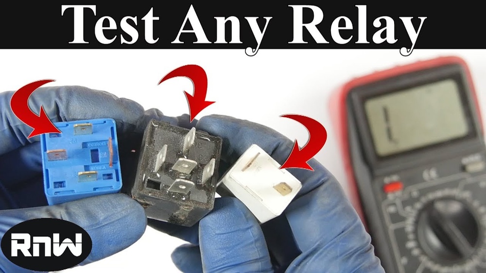
Testing a 5 pin relay with a multimeter is a fundamental skill for anyone interested in automotive repair, electronic projects, or troubleshooting electrical systems. Relays are the silent workhorses behind the scenes, controlling circuits too powerful or complex for switches alone.
Despite their compact size, a faulty relay can lead to frustrating electrical issues, anything from a car’s headlights refusing to turn on, to major appliances failing unexpectedly. For beginners and advanced users alike, mastering relay testing is both empowering and cost-effective, enabling accurate diagnoses and repairs without guesswork.
Many people, even those comfortable with basic electronics, find relays intimidating. Their multiple pins, internal switching mechanisms, and often cryptic diagrams can be confusing at first glance. But with the right guidance and a trusty multimeter, anyone can confidently test a 5 pin relay.
This comprehensive guide breaks down the process step by step, explaining not just the “how,” but also the “why” behind each action. Whether you’re a hobbyist, a professional technician, or a curious DIYer, this article will equip you with practical methods, troubleshooting strategies, and pro tips to handle relays with confidence.
Key Takeaways
- 5 pin relays are common in automotive and industrial circuits; knowing how to test them is crucial for troubleshooting.
- Testing involves checking the coil resistance, switching function, continuity, and diagnosing common faults using a multimeter.
- Both beginner-friendly steps and advanced troubleshooting methods are covered.
- Real-world examples, tables, and diagrams are included to support understanding.
- Readers will learn to interpret relay pinouts, perform accurate tests, and avoid common mistakes.
- Proper testing can prevent unnecessary replacements and help track down elusive electrical faults.

Credit: www.kynix.com
Understanding 5 Pin Relays
What Is A 5 Pin Relay?
A 5 pin relay is an electromechanical switch used to control high-current circuits with a low-current signal. It typically features five terminals: two for the coil and three for switching (common, normally open, and normally closed). When voltage is applied across the coil, the relay’s internal contacts move, changing the circuit’s state.
Why Are 5 Pin Relays Used?
5 pin relays are prevalent in automotive applications (headlights, fuel pumps), industrial controls, and home automation. Their design allows for flexible switching, one relay can control two circuits or toggle between outputs depending on the wiring.
Relay Pinout And Symbols
Understanding the pinout is crucial before testing:
- 85 & 86: Coil terminals (for activating the relay)
- 30: Common terminal (input power)
- 87: Normally open (NO) contact (powered when relay is activated)
- 87a: Normally closed (NC) contact (powered when relay is NOT activated)
Here’s a quick reference table:
| Pin Number | Symbol | Function |
|---|---|---|
| 85 | Coil – | Coil (negative/ground) |
| 86 | Coil + | Coil (positive/supply) |
| 30 | COM | Common input/output |
| 87 | NO | Normally open contact |
| 87a | NC | Normally closed contact |
How Does A 5 Pin Relay Work?
When voltage is applied to the coil pins (85 and 86), a magnetic field forms, pulling an internal switch. This action transfers the connection from 87a (NC) to 87 (NO), allowing current to flow through the intended circuit. When the coil is de-energized, the relay returns to its default state.
Common Applications
- Automotive: Headlights, air conditioning, power windows
- Industrial: Motor control, safety circuits
- Home Automation: Lighting, HVAC controls
Example: In my experience troubleshooting a non-working car horn, a faulty 5 pin relay was the culprit. After testing and replacing the relay, normal function was restored, a simple fix that saved hours of guesswork.

Credit: www.youtube.com
Tools And Preparation For Testing
Essential Tools
To test a 5 pin relay, you will need:
- Digital multimeter (with continuity, resistance, and voltage settings)
- 12V DC power supply (optional, for advanced testing)
- Test leads and jumper wires
- Relay socket or test board (optional)
- Protective gloves and safety glasses (for automotive work)
Multimeter Basics
A multimeter is a versatile device that measures voltage, current, and resistance. For relay testing, the continuity and resistance (ohms) settings are most commonly used.
Pro Tip: Always ensure your multimeter’s battery is fresh to avoid false readings.
Safety Precautions
- Disconnect power from the circuit before removing or testing the relay.
- Avoid touching relay terminals while powered.
- Use insulated tools to prevent shorts.
- For automotive relays, remove the key from the ignition and disconnect the battery if necessary.
Locating And Identifying The Relay
- Refer to the vehicle or device’s wiring diagram or relay map.
- Identify the 5 pin relay by its pin configuration and markings.
- Gently remove the relay from its socket; avoid prying, which can bend pins.
Example: On many cars, the fuel pump relay is a 5 pin type, typically located in the fuse box under the hood. Always consult the owner’s manual or service documentation.
Step 1: Visual Inspection And Pin Identification
Visual Inspection
Before using a multimeter, a thorough visual check can reveal:
- Burn marks
- Corrosion or rust
- Melted plastic
- Loose or bent pins
Relays showing any of these signs are likely faulty and may not need further testing.
Identifying Pins
Examine the relay’s case or datasheet for a diagram. If unclear:
- Pin 85 and 86 are usually parallel and smaller.
- Pin 30 is often in the center.
- Pin 87 and 87a are on opposite sides.
Use the relay’s part number to look up the datasheet for precise identification. For a beginner, matching the pin layout to a diagram helps prevent mistakes.
| Test Step | What to Look For | Next Action |
|---|---|---|
| Visual Inspection | Burns, corrosion, distortion | Replace if found |
| Pin Identification | Match to datasheet | Label pins for testing |
Pro Tip: Use A Permanent Marker
For beginners, mark the pins as you identify them. This reduces confusion and speeds up the testing process.
Case Study: Melting And Burn Marks
A customer brought in a relay with a melted case after their headlights failed. The visual inspection revealed the issue immediately, no testing was needed, and a replacement solved the problem.

Credit: www.etechnophiles.com
Step 2: Testing The Coil Resistance
Why Test The Coil?
The coil is the heart of the relay. If it’s open or shorted, the relay cannot operate. Testing coil resistance is a quick way to check for internal faults.
How To Test Coil Resistance
- Set your multimeter to the ohms (Ω) setting.
- Connect the probes to pins 85 and 86 (the coil terminals).
- Read the resistance value.
Most 12V relays should show a resistance between 50 and 200 ohms. Consult the datasheet for exact values.
Interpreting Results
- Normal resistance (50-200Ω): Coil is healthy.
- Infinite resistance (OL): Coil is open, relay is faulty.
- Near zero resistance (short): Coil is shorted, replace the relay.
Example: Unexpected Readings
When I tested a stubborn relay, the coil measured 0.8 ohms, far too low for a 12V relay. This indicated an internal short, confirmed when the relay overheated during use.
Comparison Table: Typical Coil Resistance Values
| Relay Voltage | Expected Coil Resistance (Ohms) | Status |
|---|---|---|
| 6V | 30 – 60 | Normal |
| 12V | 50 – 200 | Normal |
| 24V | 200 – 1000 | Normal |
Advanced Suggestion: Testing Under Load
For advanced troubleshooting, power the relay coil with a variable supply and measure current draw. Excessive current indicates a partial short; no current means an open coil.
Step 3: Checking The Normally Closed (nc) And Normally Open (no) Contacts
Understanding No And Nc Contacts
- Normally Closed (NC, pin 87a): Connected to common (pin 30) when relay is OFF.
- Normally Open (NO, pin 87): Connected to common when relay is ON.
Testing these contacts verifies the relay’s switching function.
Testing Continuity (nc Contact)
- Set multimeter to continuity mode (beep icon).
- Connect probes to pin 30 and pin 87a.
- With the relay unpowered, you should hear a beep or see near-zero resistance (<1Ω).
No continuity means the contacts are worn or burned.
Testing Continuity (no Contact)
- With the relay unpowered, connect probes to pin 30 and pin 87.
- No beep or high resistance (>1MΩ) should be observed, this is normal.
Example: Real-world Fault
A relay with burned contacts failed the NC test, the multimeter showed infinite resistance between pins 30 and 87a. Replacing the relay restored function.
Advanced Suggestion: Contact Resistance Measurement
For mission-critical applications, measure the actual resistance across contacts. Values above 0.1 ohms suggest worn or pitted contacts, which can cause voltage drops and unreliable operation.
Step 4: Energizing The Coil And Observing Relay Switching
Simulating Circuit Operation
To fully test the relay’s function:
- Apply 12V DC power across pins 85 and 86 (observe correct polarity).
- Listen for a click, this indicates the relay is switching.
Testing No And Nc While Energized
- With the coil powered, test continuity between pin 30 and pin 87 (NO), should now be closed (beep or low resistance).
- Test between pin 30 and pin 87a (NC), should now be open (no beep, high resistance).
Pro Tip: Use Jumper Wires
For hands-free testing, use jumper wires from a 12V battery or bench supply to energize the relay while probing contacts.
Safety Warning
Never apply voltage across the wrong pins; double-check your connections to avoid damage or injury.
Example: Troubleshooting A Stuck Relay
A relay that clicks but fails to switch contacts may have welded contacts. In one advanced electronics class, I encountered a relay with a coil that activated but contacts that didn’t move, measuring the resistance confirmed the contacts had fused together.
Advanced Suggestion: Measuring Coil Current
While energized, measure the current drawn by the coil. Compare to the datasheet value. Abnormal current suggests internal coil degradation, which may precede failure.
Step 5: Advanced Diagnostics And Troubleshooting
Diagnosing Intermittent Or Heat-related Faults
Some relays work when cold but fail under load or heat. To simulate real conditions:
- Lightly heat the relay with a hair dryer while energized.
- Observe for any loss of switching or increased contact resistance.
Vibration And Mechanical Tests
Tap the relay gently. If switching is erratic or contacts chatter, internal springs or contact points may be worn.
Checking For Coil Leakage
Set your multimeter to the highest resistance range. Measure resistance between coil pins (85/86) and contact pins (30, 87, 87a). Any reading (instead of infinite resistance) indicates insulation breakdown.
Using A Test Jig Or Relay Tester
For frequent testing, consider a relay tester or build a simple test jig. These devices automate coil energizing and contact checking, speeding up the process for workshops or advanced users.
Case Study: Industrial Control Panel
In a factory, repeated relay failures halted production lines. Advanced testing revealed excessive contact resistance due to arcing. Switching to relays with gold-plated contacts, rated for higher cycles, resolved the issue.
Comparison Table: Common Relay Faults And Symptoms
| Fault Type | Test Result | Likely Cause | Solution |
|---|---|---|---|
| Open Coil | Infinite resistance (85-86) | Burned-out coil | Replace relay |
| Welded Contacts | NO and NC both closed | Excessive load/arcing | Replace; check load |
| Pitted Contacts | High contact resistance | Overcurrent or age | Replace relay |
| Coil Leakage | Low resistance to contacts | Insulation breakdown | Replace relay |
Real-world Examples And Best Practices
Example 1: Automotive Headlight Circuit
A car owner reported intermittent headlight operation. Following the steps above:
- Visual check revealed a clean relay.
- Coil resistance measured 120Ω (normal).
- NO contact failed to close when energized.
- Replacing the relay restored headlights instantly.
Example 2: Home Automation System
A DIY enthusiast noticed their automated garden lights stayed on. Testing revealed the NC contact was permanently open, likely from a power surge. Upgrading to a surge-protected relay fixed the problem.
Example 3: Industrial Plc Panel
A manufacturer’s conveyor belt relay passed all static tests but failed under vibration. Advanced mechanical testing uncovered a weak spring. Switching to a vibration-rated relay improved reliability.
Pro Tip: Always Test Before Replacing
Many electrical faults blamed on relays are actually wiring or control issues. Testing relays as described avoids unnecessary part swaps and saves time.
Advanced Suggestions And Pro Tips
For Beginners
- Label your relay pins before testing.
- Take photos of relay wiring before removal.
- Start with continuity and resistance checks, easy and safe.
- Consult the relay datasheet for specific values and diagrams.
For Advanced Users
- Measure contact resistance with a four-wire (Kelvin) method for precision.
- Test relays under actual load conditions if possible.
- Use a relay tester for rapid diagnostics in workshops.
- For high-reliability systems, log relay cycle counts and replace on schedule.
When To Replace A Relay
- If any test fails (open coil, burned contacts, high resistance)
- If the relay shows physical damage or corrosion
- After 100,000+ cycles in critical applications (see manufacturer’s guidelines)
Further Reading
For more in-depth relay theory and application, refer to the comprehensive guide on Wikipedia or the datasheets from relay manufacturers like Omron.
Frequently Asked Questions
What Happens If I Test The Relay With The Wrong Multimeter Setting?
Using the wrong setting, like voltage instead of resistance, won’t usually damage the relay but may give meaningless results. However, applying high voltage to the wrong pins can damage both the relay and your multimeter. Always double-check your multimeter mode and consult the relay’s diagram.
Can I Test A Relay Without Removing It From The Circuit?
It is possible to test some aspects of a relay in-circuit, such as listening for a click when the control circuit is activated. However, for definitive tests, especially resistance and continuity, removing the relay avoids interference from connected components and ensures accurate results.
What If My Relay Clicks But Doesn’t Switch The Circuit?
A clicking sound means the coil is working, but the contacts may be burned, welded, or pitted. Test the NO and NC contacts with a multimeter while the relay is energized. If there’s no continuity where there should be, the contacts are faulty and the relay should be replaced.
How Do I Know If The Relay Is Suitable For My Application?
Check the relay’s voltage, current, and contact ratings on its datasheet. Using a relay with too low a rating can cause premature failure or unsafe operation. For critical or high-power circuits, always choose a relay with a margin above your circuit’s maximum requirements.
Can A Relay Fail Intermittently, And How Do I Test For This?
Yes, relays can fail intermittently, especially under vibration, heat, or high current. Simulate operating conditions: apply power, gently tap or heat the relay, and observe for changes in operation. If the relay fails or acts unpredictably during these tests, it should be replaced.
Testing a 5 pin relay with a multimeter may seem daunting at first, but with careful step-by-step checks and a basic understanding of relay operation, anyone can confidently diagnose relay faults. For beginners, start with visual inspection and simple resistance tests.
As you gain experience, try advanced troubleshooting like measuring contact resistance or simulating real-world conditions. Proper relay testing not only saves money but also enhances your overall electrical troubleshooting skills, making you more effective and confident in repairs, whether in the garage, workshop, or at home.